Schematic Diagrams
When building a circuit, it's good to have a design first. A schematic diagram is a drawing of the circuit, with wires represented by lines and special symbols used for the various electronic components. The reason we use symbols, rather than drawings of the actual parts, is because the symbols are usually simpler, easier to draw. Also, what's important is the function of the device within a circuit, not necessarily what it looks like. Batteries, for example, come in many shapes and sizes, but the role they play in a circuit is universal.
There are many different components that can be part of a circuit, and we'll become familiar with many of them later. For now, here are a few of the most basic.
to do as you read
Wire A wire is represented by a solid line. Simple enough. ________________________
Switch A switch turns a circuit on or off. You can think of it as a drawbridge for electrons: when the drawbridge is up (open), no charge can get through; when the bridge is down (closed), the current can flow. Here's the symbol used for a basic switch:

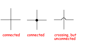
Junction Where two wires join is called a junction.
In a diagram a dot may be drawn where they connect, for emphasis, although
this really isn't necessary. If there are wires that don't
connect to each other, try not to draw them crossing on the diagram.
If it's unavoidable, make a little semi-circular loop, sort of like a little overpass, in one of the wires
to indicate that the two wires are not electrically connected.

Battery A battery provides the voltage needed to push current through a circuit. Batteries come in a variety of sizes and shapes, but they all use either of these schematic symbols:
![]()
To be nit-picky, the top symbol is not a battery, but rather a cell. The most common chemical reaction used produces a voltage of 1.5 V, and that's why the standard AA, AAA, C and D "batteries" are all 1.5 volts. Cells can be connected end-to-end ("in series") to produce higher voltages. Such a stack of cells is truly and correctly called a battery, and would use the second of the two symbols above. Car batteries have six 2-volt cells in series, for a total of 12 volts. Nine-volt batteries have a stack of six 1.5-volt cells inside that rectangular case.
Despite the distinction made between cells and batteries in the previous paragraph, the word "battery" has, in recent years, come to refer to both cells and true batteries. In circuit diagrams, which of the above symbols is used nowadays is really a matter of preference.
The short-line end of the battery symbol is always the negative end, regardless of whether the - and + labels are present.
Resistor A resistor hinders the flow of current by a specific amount. There are two different symbols used, either a zigzag line, or a rectangle. There's no difference, just a matter of personal preference.
Example Here is an example of a simple circuit schematic. It has a battery, a switch, and a lightbulb (the resistor symbol with the circle around it.)
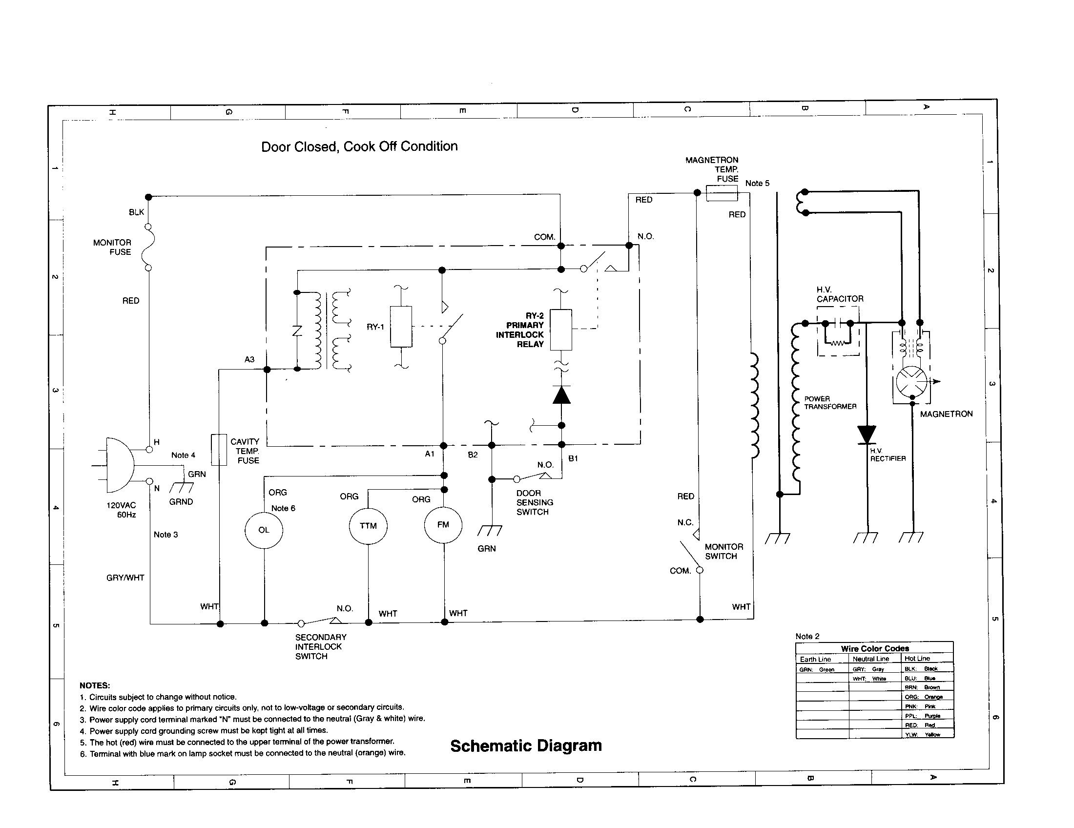
Shown below is another, more complicated example: a microwave oven. Of course, you're not expected to understand this diagram. At this point, just appreciate that the entire circuitry of a microwave oven can be summarized on a single piece of paper, and that different symbols are used to represent different parts.
Click on this picture to see it full-size.
1. Draw schematics for the following circuits:
(a) One battery, two light bulbs, and one switch that turns
them both on and off.
(b) One battery, two light bulbs, and two switches, with each switch controlling
one bulb.
(c) One battery, one light bulb, and two switches. The light bulb is ON
if either switch is on (closed).
(d) One battery, one light bulb, and two switches. The light bulb is ON only if both switches are on (closed).
You can use the Circuit Construction Kit to verify your answers.
