Using a Multimeter
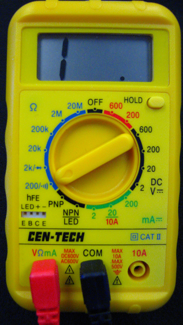
Here's a picture of a typical digital multimeter. Notice that there are three plug sockets at the bottom, but only two of them are used at a time. The black probe is always in the common (COM) socket. To measure voltage, resistance and relatively low current (up to 200 mA), the red probe is plugged into the leftmost socket. For measuring high current (up to 10A), move the red probe to the right socket. Depending on what you are trying to measure, turn the range selector dial to the appropriate position. On this multimeter, the ohmmeter ranges are marked in blue, ammeter ranges in green, and voltmeter ranges in black (DC) and red (AC). This multimeter is currently set to measure resistance, up to a maximum resistance of 200 ohms. |
|
to do as you read
Measuring Resistance
- The resistor you are measuring must be alone, not connected to a circuit, in order to get a valid measurement of its resistance.
- Select a range greater than the expected resistance. If you have no idea what the resistance is, select the highest range.
- Connect one lead to each end of the resistor. Which one is connected to which side is not important.
- The reading is in whatever units (ohms, kilohms or megohms) that the range setting is labeled.
Measuring Voltage
- Work on the circuit as it is operating, with no alterations.
- Select a range greater than the expected voltage, and whether the it's AC or DC. If you have no idea what the voltage is, select the highest range.
- Voltage measurements are always measures of voltage differences.
- Whenever we speak of "the voltage" at a certain point in a circuit, that is really the voltage difference above ground, a reference location in the circuit. Usually ground is the negative terminal of the battery or power supply. Connect the black lead to the ground location, and the red lead to whatever point in the circuit you are measuring.
- Whenever we speak of a "voltage drop through" or "the voltage across" a component, that means you are finding the difference in voltage between the two sides of the component. Attach one lead to each side of the component. If the multimeter reads a positive voltage, the red lead is the higher voltage; if the meter reads negative, the red lead is the lower voltage.
In other words, you are hooking up the multimeter in parallel with the component whose voltage you are measuring. In voltage-measuring mode, the multimeter itself has a very high resistance (millions of ohms), so hardly any current goes through the multimeter itself, and it shouldn't affect the circuit.
Measuring Current
- Select a range greater than the expected current, and whether it's AC or DC. If you have no idea what the current is, select the highest range.
- Work on the circuit as it is operating. Break the circuit at the point you want to measure the current.
- Attach one lead to one of the broken ends, and the other lead to the other side of the break.
In other words, to measure the current flowing through a particular point in the circuit, you are inserting the multimeter in series with the circuit. The current must flow through the multimeter. When set to current-measuring mode, the multimeter itself has essentially zero resistance. The current flows through it pretty much as it would through a wire and doesn't (or shouldn't) affect the operation of the circuit.