Logic Gates
Read the Logic Gates notes located at http://www.kpsec.freeuk.com/gates.htm
Download and run the Parallax Logic Simulator (Windows only.)
Vocabulary words discussed in class that you should know:
Integrated circuit (IC), also known as a chip. A piece of silicon onto which is printed a circuit containing many tiny transistors, capacitors, resistors and diodes. The silicon circuit is protected inside a rectangular plastic package (usually black in color) with metal wires (called pins) protruding, allowing connections to other chips or circuits.
Pinout: a diagram showing the function of each of the pins of an integrated circuit
Logic gates: circuits that take binary inputs and perform the functions as defined below
NOT: inverts the input. Input LOW produces output HIGH, and vice versa. Also known as an inverter.
AND: output is HIGH only if all the inputs are HIGH.
NAND: output is LOW only if all the inputs are LOW; same as AND, except the output is inverted
OR: output is HIGH if any input is HIGH
NOR: output is HIGH if any input is LOW; same as OR, except output is inverted
XOR: output is HIGH if one, and only one, input is HIGH
XNOR: output is LOW if one, and only one, input is HIGH; same as XOR, except output is inverted
Truth table: A table listing the output for all possible inputs.
Flip-flop, also known as a latch: a one-bit memory circuit.
Set: to make a wire or latch have a HIGH value
Reset: to make a wire or latch have a LOW value
Bus: a group of wires carrying a set of related signals from one place to another in a circuit. For example, a data bus would carry the 16 bits of a word on 16 separate wires, from the RAM to/from the CPU. A separate address bus would specify which word in memory is being read or written.
Register: a group of latches that serve as memory. Eight latches form a one-byte register.
Random Access Memory (RAM): many registers on a single chip, used to store many binary numbers. Any one of these registers can be read or written by placing its address on an address bus, and the data to be read/written on the data bus. The "random access" part of the name means the data don't have to be read in order; you can access any register at any time. This is in contrast to sequential access memory systems, such as magnetic tape.
CPU (short for Central Processing Unit): The "processor" of a computer. The thing that does the computing.
Trigger: A signal that causes a digital circuit to perform a particular function. Triggers can be one of two types:
Rising Edge: a transition from LOW to HIGH triggers the action
Falling Edge: a transition from HIGH to LOW triggers the action
Counter: a circuit with an output register containing a binary number. Each time the counter is triggered, the output is incremented (increased by one).
Multiplexer: a circuit with several (or many) inputs, and one output. Depending on control signals, one of those input signals is routed to the output.
Demultiplexer: a circuit with one input and several (or many) outputs. Depending on control signals, the input is routed to one of the outputs.
Additional Activities & Practice
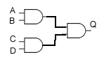
1. Create a truth table for the following network of logic gates.
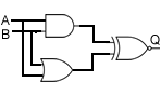
2. Create a truth table for the following network of logic gates.
3. Draw a network of three logic gates, then create a truth table. A NAND gate takes two inputs, A and B. Inputs C and D feed into an XOR gate. The outputs of these two gates then feed into an OR gate.
4. Draw a network of three logic gates, then create a truth table. A NOR gate takes two inputs, A and B. Input C goes into a NOT gate. The outputs of these two gates then feed into an NAND gate.