Electronic Components
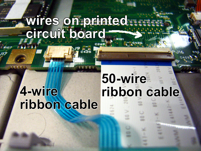
Wire A wire is the simplest electronic component — just a long, narrow conductor allowing current to flow when there is an electric field (or voltage difference) to push the electrons through whatever resistance there is. Simple idea, but in real circuits the wires can take a few surprising forms. Printed circuit boards (PCBs) have the wires printed on a flat board. Other components (such as capacitors, resistors, integrated circuits and the other things listed below) are mounted into holes on the PCB and connected to the printed wires by solder. A cable is a group of wires bundled together, allowing many individual wires to be connected by plugging in a single cable. A ribbon cable is a flat cable, often used to connect two separate PCBs in a sophisticated device like a laptop computer.
Regardless of whether a wire is discrete (alone), part of a cable, or on a printed circuit board, in a schematic diagram it is still represented as a thin solid line.
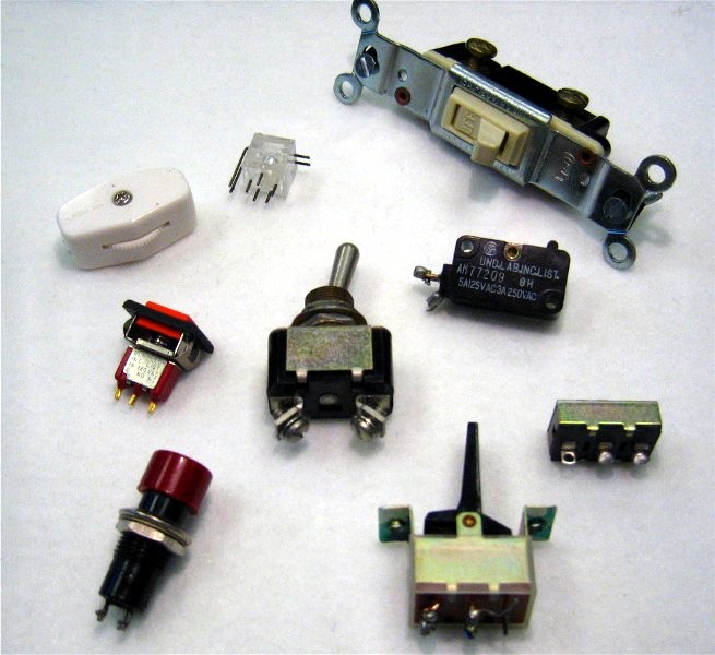
Switch The simplest kind of switch just turns a circuit on or off. You can think of it as a drawbridge for electrons: when the drawbridge is up (open), no charge can get through; when the bridge is down (closed), the current can flow. This kind of switch is called a single-pole/single-throw switch, usually just abbreviated SPST. The schematic symbol, which you've seen before, is below. It connects a single wire (on the left) to a single wire (on the right), or not. Notice that SPST switches have only two contacts (connections).
A basic home light switch is a SPST switch. The applet at right illustrates how it works. When switched "off", the plastic lever that you move with your finger pushes a flexible metal bar, breaking contact with another piece of metal.
Another kind of switch is the single-pole/double-throw (SPDT). A SPDT switch can connect a single wire (the "pole" or "common") to either of two other wires. The schematic symbol, below, shows that wire A (the common) can be connected to either wire B or wire C, depending. You can tell a switch is SPDT if it has three contacts.
Yet another kind is the double-pole/double-throw (DPDT) switch. The schematic symbol is below. A DPDT switch is just two SPDT switches in one package. The two "drawbridges" are connected mechanically (represented by the dotted line), so when one flips the other flips as well. Wire A is connected to wire B at the same time wire D is connected to wire E. With a flip of the switch, A is connected to C and D is connected to F. There is no electrical connection between A and D. If a switch has six contacts, it is DPDT.
Some switches are momentary: when you press them they switch, but when you let go they go back to their original position. Push-button switches usually fall into this category. Momentary switches can be SPST, SPDT, or DPDT. The contacts are usually labeled COM or COMMON (for contacts A and D in the diagrams above), NORMALLY CLOSED or NC (for contacts B and E above) and NORMALLY OPEN or NO (for contacts C and F above). "Normally" means that nothing is pressing the switch. When unpressed, the COMMON contacts are connected to the NC contacts; when pressed, the COMMONS are connected to the NO contacts.
Copyright David M. Harrison, University of Toronto.
Used with permission under Creative Commons License.
1. Two common examples of pushbutton SPST switches around the home are the buttons that ring the doorbell, and that control the light inside a refrigerator. One of these is NC and the other NO. Which is which? Explain.
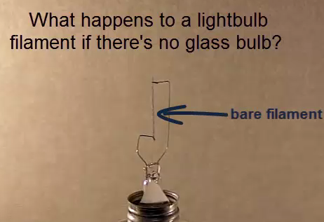
Why does a lightbulb have the glass on the outside? Watch this video to find out?
Solenoid A solenoid is an electromagnet that, when current is sent through it, pulls a metal plunger. That plunger can be attached to part of a machine, so it pulls a lever, strikes a bell, or pushes on some mechanism.
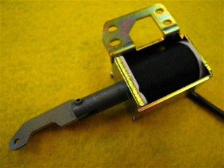
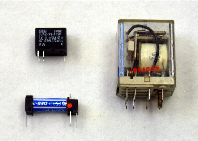
Relay A relay is a electrically-operated switch. Rather than a lever, slider or push-button that is moved by hand, a solenoid "flips the switch". Because relays are just a special kind of switch, they come in the same varieties as mechanical switches: SPST, SPDT, DPDT.
Fuse ![]()
If too much current flows through a circuit (because too many devices are attached to it in parallel, or there's a short circuit somewhere) there is the danger of wires overheating and catching fire. A fuse is a piece of wire that is designed to melt — safely — when a certain specified current flows through it. Placed in series with the power supply, when the wire melts, the circuit is broken and all current flow stops. For example, a 2A fuse will melt ("blow") when 2 amps of current flow through it.
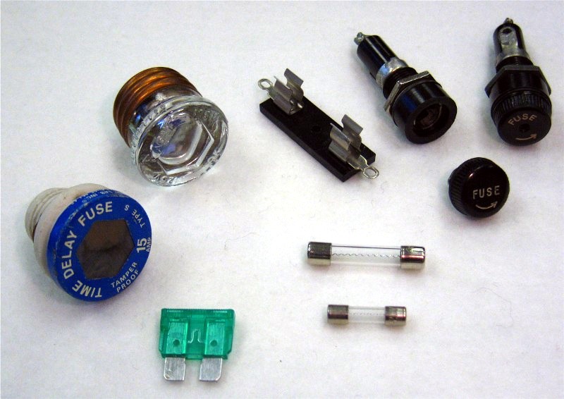
In the photo at right, the two round, screw-in fuses on the left are the type that used to be common in houses (circuit breakers are now used instead). The green fuse is the type used in cars. The two clear, cylindrical fuses are typical of fuses used in individual pieces of electronic equipment, like computers and audio systems. In the upper right of the photo are holders for the cylindrical fuses, allowing them to be quickly and easily replaced when necessary.
Once "blown", a fuse must be replaced in order to get the circuit working again. But before doing that, make sure you fix whatever the problem was that caused the current to be so high.
Circuit Breaker
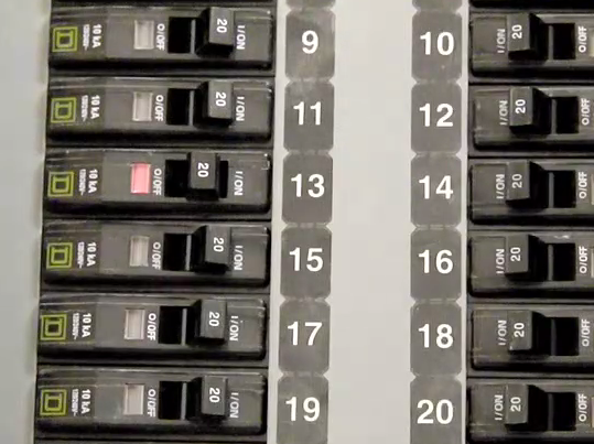
A circuit breaker serves the same purpose as a fuse — it breaks a circuit that has too much current flowing through it, stopping what could be a dangerous situation. How it does this is completely different, though. A circuit breaker is essentially a switch that turns itself off when too much current flows through it. The advantage of this is that, once the short circuit or other problem has been fixed, the circuit can be turned back on by manually flipping the lever back to the ON position. The circuit breaker doesn't have to be replaced, like a fuse would.
A 1-minute video on circuit breakers.
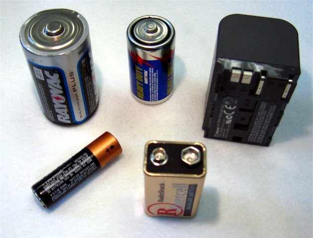
Battery A battery (or cell) provides the voltage needed to push current through a circuit. Batteries come in a variety of sizes and shapes, but they all use either of these schematic symbols:
![]()
Batteries connected end-to-end (i.e. in series) produce a higher voltage. The calculator most commonly used in my classes has four 1½-volt batteries in series, yielding 6 volts. Less commonly, batteries can be connected in parallel. This results in the same voltage as a single battery by itself, but a higher maximum current capability.
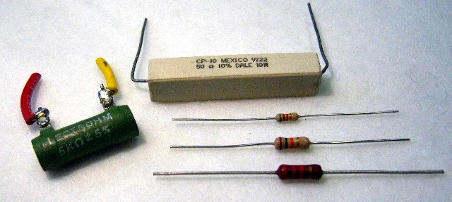
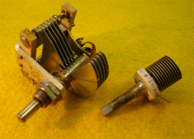
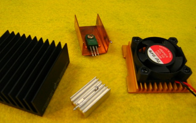
Potentiometer or Variable Resistor 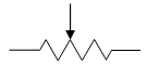
A potentiometer is a resistor whose resistance can be changed, usually by turning a shaft or knob. It will be labeled or specified by its maximum resistance; for example, a 50 kΩ potentiometer will have a resistance ranging from a few ohms up to 50,000 ohms, depending on the turn of the know.
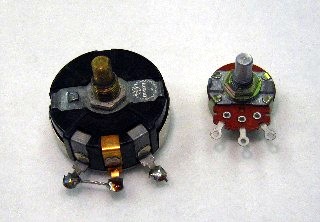
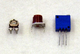
To the right, the two large "pots" in the upper photo are the type that the user of a piece of electronics might directly turn — to adjust the volume of sound, for example. These pots are intended to be used often and part of the function of the circuit. The three small "trim pots" in the lower photo would be mounted on a circuit board and would be used only rarely, by a technician at the factory or repair shop to adjust some part of a large circuit.
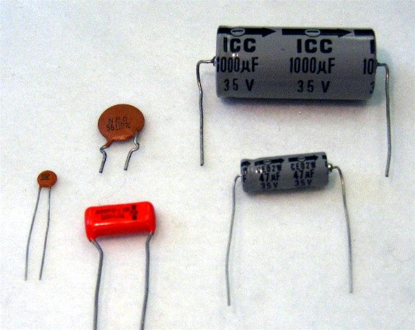
Capacitor 
A capacitor is a device that can store charge. They are made by having two conductive plates very close to each other, but not touching. The greater the area of the plates, the more charge can be stored. Most capacitors use a thin metal film for the plates, separated from each other by an insulator such as paper, mica, or teflon. This metal-insulator-metal sandwich can then be rolled up into a small package.
Most types of capacitors are unpolarized, meaning that they can be connected into a circuit either way. One prominent type, though, so-called electrolytic capacitors, have a positive and negative end, and have to be put into the circuit with the positive lead at a higher voltage than the negative lead. The two grey capacitors on the right side of this photo are of this type.
Variable Capacitor 
The ability of a capacitor to store charge is called its capacitance, and that depends on the size of the metal plates and how close they are to each other. Variable capacitors can have their capacitance changed by turning a knob: the shaft moves sets of metal plates so they overlap each other differing amounts. It's kind of like changing the size of the plates.
When you use any piece of electronics, if you are turning a knob you are usually turning either a potentiometer or a variable capacitor.
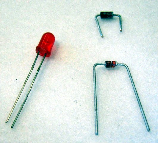
Diode ![]()
A diode is a device that conducts electricity in only one direction. Here's a video that illustrates what I mean:

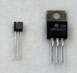
Transistor ![]()
Transistors have three leads (wires). One of them, called the base, controls the passage of current between the other two leads, called the emitter and collector. In other words, a transistor can be used like a relay, where the voltage put on the base (by other parts of the ciruit) can turn on or off the current between the emitter and collector. An advantage a transistor has over a relay is that the base requires very little current in order to turn on the emitter-collector current; a traditional relay uses an electromagnet (solenoid) to switch on, and that requires a relatively large amount of current.
Transistors can also be used as amplifiers. In the transition region where the base voltage is on the verge of turning on the emitter-collector current, a very small change in base voltage or current causes a large change of the emitter-collector current. A small change in one circuit, that causes a large change in other — that is the essence of what an amplifier is.
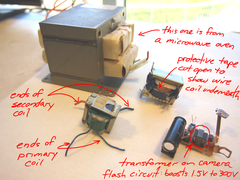
Transformer Transformers use magnetic fields to change an AC voltage. A transformer consists of two electromagnet coils (called the primary coil and secondary coil) next to each other, so that the magnetic field of one goes through the other. Usually, a heavy iron core is used to enhance the effect. When the AC current sent through the primary changes polarity, its magnetic field changes as well. This fluctuating magnetic field induces current in the secondary coil. The AC in the secondary will have the same frequency as the AC sent into the primary, but the voltage will be different, depending on which coil has more windings (loops of wire). If the secondary has more loops than the primary, the AC voltage output from the secondary will be higher than the voltage input to the primary. That would be a step-up transformer. Conversely, if the secondary has fewer loops than the primary, the output from the secondary will be lower voltage than the input voltage to the primary — a step-down transformer. If Nprimary and Nsecondary are the number of wire loops on the primary and secondary coils, respectively, then...
![]()
Remember, transformers only work for AC!
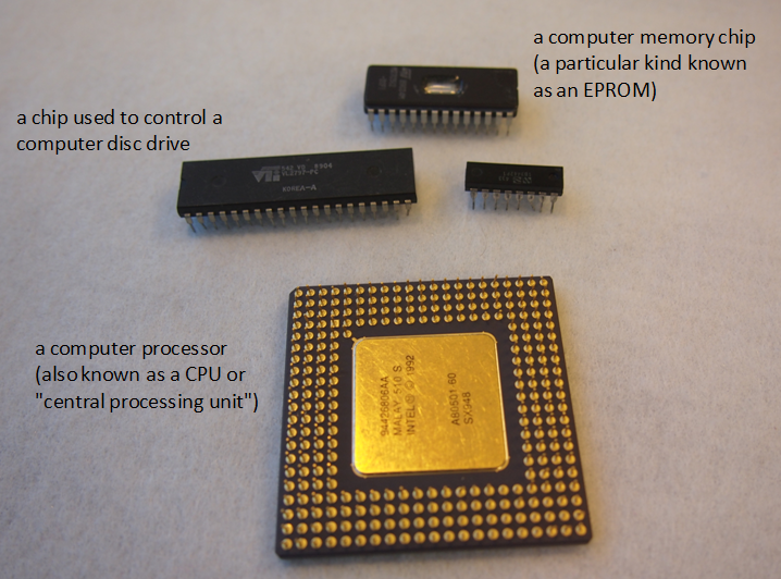
Integrated Circuits
All of the above items are discrete. That is, single items, as opposed to collections or groups. However, it is possible to create on a single substrate (base surface) many, many components, each one of which is microscopic, forming very complex circuits. Usually, the substrate is silicon (element #14 on the periodic table); you may have heard of "Silicon Valley", the region of California where a lot of electronics and computer companies are located. Most of the items printed on silicon chips are resistors, capacitors and transistors. A very complex circuit, like a processor for a computer, might have billions of components printed on a silicon chip the size of your thumbnail. Another name for a chip is integrated circuit, or IC.