Capacitors
Capacitors are devices that store an electrical charge and, in storing that charge, also store energy (as electrical potential energy).
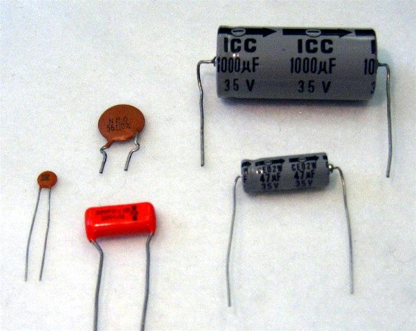
Here is what some typical capacitors look like:
The symbols for a capacitor, used in schematic circuit diagrams, are either of these:
![]()
![]()
The greater the voltage of the battery, the greater the charge that could be forced onto the capacitor plates. In other words, the charge is proportional to the voltage difference across the capacitor.
![]()
We can make that proportionality an equality by inserting a constant of proportionality, the capacitance, C.
![]()
The capacitance describes the ability of the capacitor to store charge, regardless of how much charge happens to be on it at any given moment. The SI units of capacitance are coulombs per volt, coul/V, but this is used so often that a special name has been given to it, namely the farad, symbol: F. (The name is in honor of 19th-century physicist Michael Faraday.)
A capacitor with capacitance of 1 F would have 1 coulomb of charge on it for each volt of potential it is hooked up to. Hook a 1 F capacitor to a 9-volt battery, and a total of 9 coulombs would be stored in the capacitor. The same cap connected to a AA battery (1.5 volts) would only have 1.5 coulombs put in it.
Truth be told, a farad is a huge capacitance. (A coulomb is a very large charge, and one volt is a small potential.) Most capacitors have capacitances in the picofarad (1 pF = 10-12 F), nanofarad (1 nF = 10-9 F) or microfarad (1 µF = 10-6 F) ranges.
Activities & Practice
to do as you read
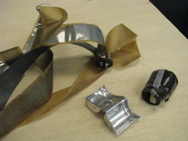
How are capacitors made?
Examples
1. How much charge is stored on a 47 µF capacitor when hooked up to a car battery (12 volts)?
Use ![]() and plug in 47x10-6 F for C, and 12 V for V. Charge stored is 5.6x10⁻⁴ coul.
and plug in 47x10-6 F for C, and 12 V for V. Charge stored is 5.6x10⁻⁴ coul.
2. What is the capacitance of a capacitor that stores 25 millicoulombs when connected to six AAA batteries in series?
Use
, and solve for C, yielding
.
Plug in 0.025 coulombs for the charge, and 9 volts (6 times 1.5) for the voltage, yielding the capacitance = 0.0028 farads.
1. In the photo at the top of the page, the upper-right capacitor has a capacitance of 1000 µF and a working voltage of 35 V. What is the most charge it can store?
2. You find a capacitor that is not labeled. You hook it up to a 12-volt battery and determine that it stored 45 nC of charge. What is the capacitance?
Capacitors wired in series and parallel.
When two or more capacitors are connected to each other at both ends, they are wired in parallel. Here's a schematic diagram. All the left-hand plates are connected to each other, making a bigger plate effectively, and ditto for the right-hand plate. From this perhaps you can see that capacitors wired in parallel act like a larger capacitor. Capacitances in parallel add together. They all have the same voltage applied to them (because they’re in parallel — connected directly to the voltage source).

On the other hand, when capacitors are wired in series, they do not all have the same voltage across them, but they do all have the same charge, q, as each other.
Starting with the loop rule, the voltage of the battery must equal the sum of the voltages across the capacitors.
To summarize, capacitances in series combine together like resistances in parallel, and capacitances in parallel combine like resistances in series.
Maximum working voltage
If the voltage on a capacitor gets too large, arcing (sparks) may occur between the two plates. Not only will this dissipate the stored charge, but it can also physically damage the capacitor and maybe also other parts of the larger circuit. Each capacitor, therefore, has a maximum working voltage that should not be exceeded. As long asyou don't exceed that voltage, you are not in any danger of damaging the capacitor.
Additional Activities & Practice
3. The capacitor inside the flash unit of a disposable camera has a capacitance of 120 µF.
(a) If it is charged up the voltage of the battery, 1.5V, how much charge would be stored on the capacitor?
(b) The answer to question (a) is not nearly enough charge to fire the flash. The flash requires about 35 millicoulombs of charge, so the electrical engineers designing the flash use a transformer circuit to boost the voltage high enough to get that much charge on the capacitor. How high does the voltage need to be?
4. In the photo at the top of the page, the smaller of the two gray capacitors has a capacitance of 47 µF and a working voltage of 35 V. Can you safely use this capacitor to store one millicoulomb of charge?
5. You have a bunch of medium-size capacitors, but you need a larger capacitance. Do you connect the capacitors in series or parallel?
6. You have three capacitors: 470 pF, 1000 pF, and 22 nF. What is their combined capacitance if you wire them (a) in series, and (b) in parallel? Give both your final answers in both pF and nF.
Check your answers.