Power Adapters
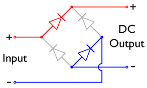
An AC power adapter (also sometimes called a "wall wart" or "brick") is used to convert standard AC outlet electricity (120-volt 60-Hz AC, in the U.S.) into a lower, DC voltage. They are used to power or recharge many electronic devices, such as cell phones, computer speakers, and radios. For example, this AC adapter (photo to the right) outputs 9 VDC and was originally used to power a wireless telephone. How does it work? See the schematic diagram, below, or the video. The 120 VAC is reduced with a step-down transformer. The output of that is also AC, of course, so it needs to be converted to DC next. That job is done by the rectifier bridge circuit, consisting of 4 diodes wired in a diamond pattern. The AC is input to the rectifier bridge at the top and bottom corners, numbered 2 and 4 in the diagram. The DC output is at the left and right corners (labels 1 and 3). There's a small problem, though --- even though the output of the rectifier bridge doesn't switch direction, the voltage isn't constant either. A capacitor at the very end "smoothes" the output to a constant DC voltage. |
 |
Here's a video that explains and demonstrates how a basic AC adapter works. (Link to same video hosted on YouTube.)
Here's the schematic diagram of the basic AC adapter.

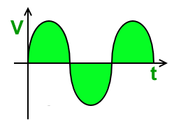
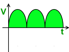
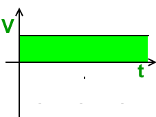
| This is what the input voltage to the AC adapter looks like. The output of the transformer looks the same, only with smaller peak voltage. | This is the output of the rectifier bridge, if the smoothing capacitor wasn't present. | This is the smooth output, thanks to the capacitor. (image source: Wikimedia Commons) |
How does the bridge rectifier work?
You can think of a diode as a switch, that turns itself on (conducts) when the anode (the wire at the blunt end of the diode symbol) is more positive than the cathode (the pointy end of the diode symbol). The input wires of the rectifier bridge, coming from the transformer, are alternating in polarity. The first diagram below shows a particular moment when the top input wire is positive and the bottom input wire is negative. At this moment, the top-left and bottom-right diodes are conducting, because for these two diodes the anode is more positive than the cathode. The other two diodes are off, so the top input wire is connected to the top output wire. Half a period later (second diagram below), when the top input wire is negative and the bottom positive, the bottom-left and top-right diodes are the ones that are on. Now the top input wire is connected to the bottom output wire. The net result is that when the input switches polarity, the wire connecting to the output wires are swapped. The top output wire is always positive. (image source: Wikimedia Commons)

How does the smoothing capacitor work? The output of the rectifier bridge by itself doesn't change polarity, but does vary in voltage from zero up to some maximum. When the voltage tries to rise above the average voltage, the capacitor soaks up the extra current. When the voltage tries to fall toward zero, the capacitor fills in the gap, releasing current into the output wires and keeping the voltage very nearly constant. Another way to think of that process is that the charge stored on - and the voltage across - a large capacitor cannot change rapidly. Most AC adapters also have a high-resistance "bleeder resistor" placed parallel to the smoothing capacitor. This allows the capacitor to discharge when the AC adapter is unplugged, so no one gets a shock if they unplug the adapter and happen to touch the blades of the plug. |
Here is a picture of the insides of the AC adapter pictured at the top of the page. |

Additional Activities & Practice
1. Here is the label on an AC adapter. (a) What is the turns ratio of the transformer? (b) Does this have a rectifier or not? (c) What is the maximum power this thing can provide?
|
 |